Discontinuous versus Continuous Models
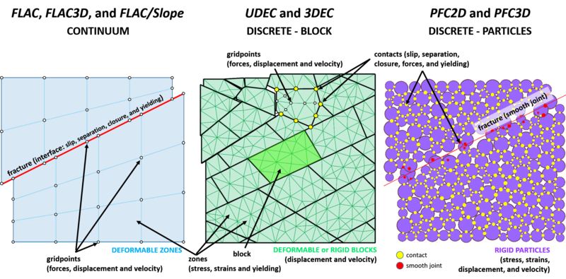
A discontinuous medium is distinguished from a continuous one by the existence of contacts or interfaces between the discrete bodies that make up the system. Discontinuum methods can be categorized both by the way they represent contacts and by the way they represent the discrete bodies in the numerical formulation.
Distinct Element Method
The distinct element method (DEM) is a numerical solution used to describe the mechanical behavior of discontinuous bodies. Introduced by Peter Cundall (1971), the DEM was developed for the analysis of rock mechanic problems using deformable polygonal-shaped blocks and then applied to soils (Cundall and Strack, 1979). This led to the development of Itasca's UDEC (Universal Distinct Element Code) and 3DEC (Three-Dimensional Distinct Element Code) software. PFC is a simplified implementation of the DEM because it utilizes rigid disks (PFC2D) or spherical particles (PFC3D) to simplify contact detection greatly between elements for faster model solutions.
Solution Cycle
This is a dynamic process in which the speed of propagation depends on the physical properties of the discrete system. The dynamic behavior is represented numerically using a time-stepping algorithm in which it is assumed that the velocities and accelerations are constant within each time step. The solution scheme is identical to that used by the explicit finite-difference method for continuum analysis. The DEM is based upon the idea that the time step chosen may be so small that during a single time step, disturbances cannot propagate further from any particle than its immediate neighbors. Then the forces acting on any particle are determined exclusively at all times by its interaction with the particles with which it is in contact. Since the speed at which a disturbance can propagate is a function of the physical properties of the discrete system, a time step can be calculated to satisfy this constraint. The use of an explicit, as opposed to an implicit, numerical scheme makes it possible to simulate the nonlinear interaction of a large number of particles without excessive memory requirements or the need for an iterative procedure. The calculations performed in the DEM alternate between the application of Newton’s second law to the particles and a force-displacement law at the contacts. Newton’s second law is used to determine the motion of each particle arising from the contact and body forces acting upon it, while the force-displacement law is used to update the contact forces arising from the relative motion at each contact. The presence of walls in PFC requires only that the force-displacement law account for ball-wall contacts. Newton’s second law is not applied to walls, since the wall motion is specified by the user.
The calculation cycle in PFC is a time-stepping algorithm that requires the repeated application of the law of motion to each particle (or ball), a force-displacement law to each contact and a constant updating of wall positions. Contacts, which may exist between two balls, or between a ball and a wall, are formed and broken automatically during the course of a simulation.
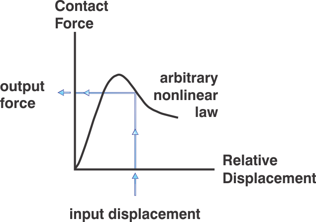
At the start of each time step, the set of contacts is updated from the known particle and wall positions. The force-displacement law then is applied to each contact to update the contact forces based on the relative motion between the two entities at the contact and the contact constitutive model. Next, the law of motion is applied to each particle to update its velocity and position based on the resultant force and moment arising from the contact forces and any body forces acting on the particle. Also, the wall positions are updated based on the specified wall velocities.
What is the difference between distinct element and discrete element?
Many finite element, boundary element and Lagrangian finite difference programs have interface elements or “slide lines” that enable them to model a discontinuous material to some extent. However, their formulation usually is restricted in one or more of the following ways:
- The logic may break down when many intersecting interfaces are used
- There may not be an automatic scheme for recognizing new contacts
- The formulation may be limited to small displacements and/or rotation (such programs usually are adapted from existing continuum programs)
The name “discrete element method” applies to a computer program only if it:
- Allows finite displacements and rotations of discrete bodies, including complete detachment
- Recognizes new contacts automatically as the calculation progresses
Without the first attribute, the model cannot reproduce some important mechanisms in a discontinuous medium; without the second, the model is limited to small numbers of bodies for which the interactions are known in advance. The term “distinct element method” was coined by Cundall and Strack (1979) to refer to the particular discrete element scheme that uses deformable contacts and an explicit, time-domain solution of the original equations of motion (not the transformed, modal equations).
